1. General Guidelines
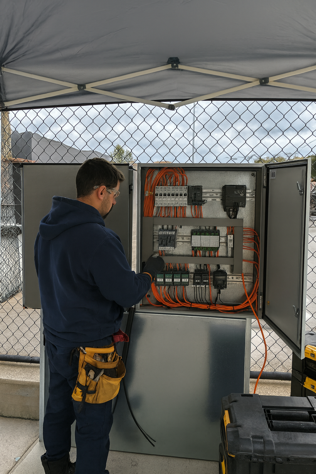
A well-executed installation from the start prevents 90% of subsequent incidents. The following principles are mandatory in any Smart Padel project.
1.1 Certified Electricians
Use only certified electricians familiar with low voltage and very low voltage control systems, specifically 12 VDC installations. The Smart Padel system operates in this voltage range and requires specific knowledge of industrial automation.
1.2 Cabling Labelling
All cabling must be clearly labelled with a functional reference. Labelling is essential for future maintenance and to facilitate remote interventions by the Smart Padel technical team.
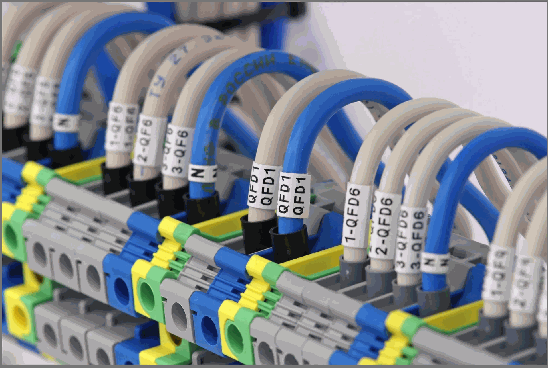
💡 Recommended labelling format Relay 1 – Court 1 Lighting | Relay 2 – Court 2 Lighting | Relay 3 – Main Access | Relay 4 – Ambient Lighting |
1.3 Cable Type
Use exclusively flexible cable with terminals (ferrules) correctly crimped on all terminals. Rigid cable may crack under pressure when inserted into screw terminals, generating poor contact and intermittent faults that are difficult to diagnose.
❌ Incorrect | ✅ Correct |
Rigid direct cable on screw terminals — may crack under pressure and cause difficult-to-diagnose intermittent faults. | Flexible cable with correctly crimped end sleeves. Recommended section: 0.75–1.5 mm². |
1.4 Cable Organisation
Cables must not be under mechanical stress or hanging freely. Arrange and secure cabling within cable trays or conduits to ensure durability and facilitate maintenance.
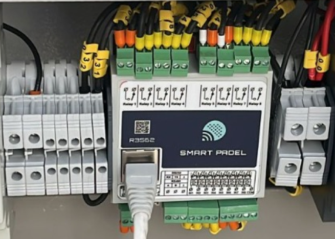
2. PLC Cabling
The SP PLC is the control core of the system. Incorrect cabling on this component may compromise the entire club automation.
2.1 Connections on PLC terminals
- Always use flexible cable with end sleeves on all PLC terminals
- Ferrules prevent loose strands, reduce oxidation and minimise short-circuit risks
- If rigid cable is used by necessity, connect it via spring terminals or push-in terminals — never directly to screw terminals
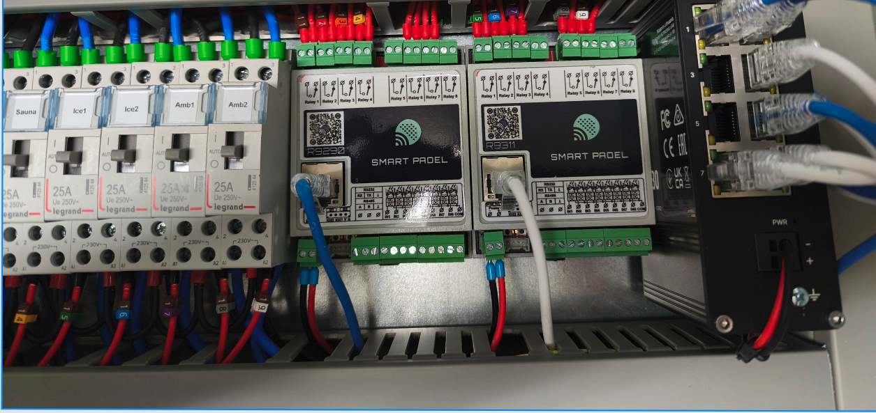
2.2 Relay Output Type
Use NO (Normally Open) relay outputs for all controlled devices. Outputs must remain open by default and only close when the system commands it, ensuring that devices are powered only when appropriate.
⚠️ Critical power rule The SP PLC relays support a maximum of 5A per output. Maglocks, door openers and lighting contactors may consume more. Always use an intermediate contactor between the PLC and the final load. NEVER connect lighting or locks directly to the PLC relay. |
2.3 Output Documentation
Each PLC relay output must be tested and documented. Keep an updated record sheet with the relay number, connected device and any relevant notes.
Relay | Connected Device | NO/NC | Notes |
|---|---|---|---|
R1 | Court 1 Lights | NO | |
R2 | Court 2 Lights | NO | |
R3 | Court 3 Lights | NO | |
R4 | Main Entrance | NO / NC* | *See Section 3 for maglocks |
R5–R8 | Free / Extension | — |
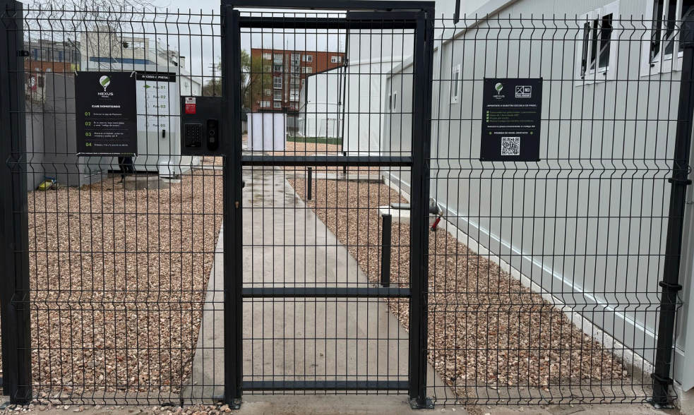
3. Access Control
The choice of lock type is a critical technical decision that must be made before installation. The lock's behaviour without power supply determines the entire wiring diagram and PLC configuration.
3.1 Key Question for the Installer
When the lock receives no power supply, what is its state? Locked or unlocked?
3.2 Types of Locks
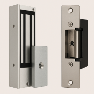
Type | De-energised state | Activation mode | Recommended use |
|---|---|---|---|
Magnetic Lock (Maglock) | FAIL-SAFE — unlocks | Requires constant 12VDC to lock. The relay cuts power to open. | Exterior padel doors, main accesses in metal frames |
Electric Strike Lock | FAIL-SECURE — remains locked | Short electrical pulse activates the coil and releases the latch. Designed for momentary activation. | Interior doors, secondary accesses with conventional frame |
3.3 PLC Configuration for Maglock
The SP PLC relays are NO (Normally Open) by factory design. To control a magnetic lock, NC behaviour is required during normal operation. This is resolved in two ways:
- Option A — Inverting relay: install an external inverting relay between the PLC and the maglock. Purely electrical solution.
- Option B — Software inversion: Smart Padel can configure logic inversion remotely, without need for additional hardware.
💡 Doors that remain unlocked for long periods (e.g. 8 hours) If the lock must remain unlocked during extended periods, add an intermediate timed relay to prevent overheating. Standard mechanical door openers are NOT designed to be continuously energised — use models with mechanical retention certified for permanent unlock mode, or replace with fail-safe maglock. |
3.4 General recommendations
- Always use an intermediate contactor or relay — maglocks can consume up to 5A
- Ensure adequate ventilation when the lock is in permanent unlock mode
- Include a manual OFF / AUTO / ON selector in the panel for local control in emergencies
- The door must always allow free exit from the inside without code or electricity — mandatory DIN EN standard
- Verify correct polarity and adequate cable cross-section to avoid voltage drops in the 12V circuit
4. Network and Communications
The Smart Padel system requires a stable local network for communication between the SP server, the PLCs and the keypads. A poorly configured network is the most frequent cause of post-installation incidents.
4.1 Network Cabling
- Use CAT6 cables for all connections between the SP Server, SP PLCs and keypads (SP Keypads)
- Maximum length per Ethernet segment: 100 metres
- Avoid Wi-Fi on critical automation components — use Ethernet for all system devices
4.2 Network Configuration
- All system devices must be on the same LAN — the system cannot function with segmented or isolated networks
- Assign static IPs or properly manage DHCP to prevent address changes that break automation
Device | Network Configuration |
|---|---|
SP Server (IP1) | DHCP — connection with router and internet |
SP Server (IP2) | Fixed IP: 10.254.254.10/24 — local automation network |
SP Keypads (Converters) | Fixed IPs: 10.254.254.11 to 10.254.254.19/24 |
SP PLCs | Fixed IPs: 10.254.254.21 to 10.254.254.29/24 |
Recommended VLAN | 10.254.254.1/24 — recommended but not mandatory |
4.3 Internet requirements
The system requires an internet connection to synchronise with Smart Padel cloud servers. However, if the connection is interrupted, the club continues to operate normally using the SP Server local storage.
- Minimum bandwidth required: 1–2 Mbps of stable outgoing connection
- It is not necessary to open inbound ports — only outbound traffic is required
- Preferred option: fibre optic
- Valid alternative: industrial 4G/5G router with SIM (Teltonika RUT200, RUT241, RUT260 or RUTX50 range)
- All communications are encrypted via VPN
✅ Internet-free operation In the event of an internet outage, the club continues to operate normally from the SP Server local storage. Master access codes continue to function. When connectivity is restored, events are automatically synchronised. |
5. Power supply
A stable and correctly sized power supply is the foundation of a reliable system. Do not skimp on this component.
5.1 Recommended power supply
- All Smart Padel components operate at low voltage (12 VDC). The recommended model is the HDR-60-12 for its proven compatibility, compact design for DIN rail and demonstrated stability in automation installations.
- Use exclusively regulated power supplies dedicated to the Smart Padel system
- Avoid sharing the power supply with other unrelated equipment
- The HDR-60-12 model is included in the SPA hardware kit
5.2 Assembly and Protection
- All system devices must be on the same LAN — the system cannot function with segmented or isolated networks
- Assign static IPs or properly manage DHCP to prevent address changes that could break automation.
Device | Network Configuration |
|---|---|
SP Server (IP1) | DHCP — connection with router and internet |
SP Server (IP2) | Fixed IP: 10.254.254.10/24 — local automation network |
SP Keypads (Converters) | Fixed IPs: 10.254.254.11 to 10.254.254.19/24 |
SP PLCs | Fixed IPs: 10.254.254.21 to 10.254.254.29/24 |
Recommended VLAN | 10.254.254.1/24 — recommended but not mandatory |
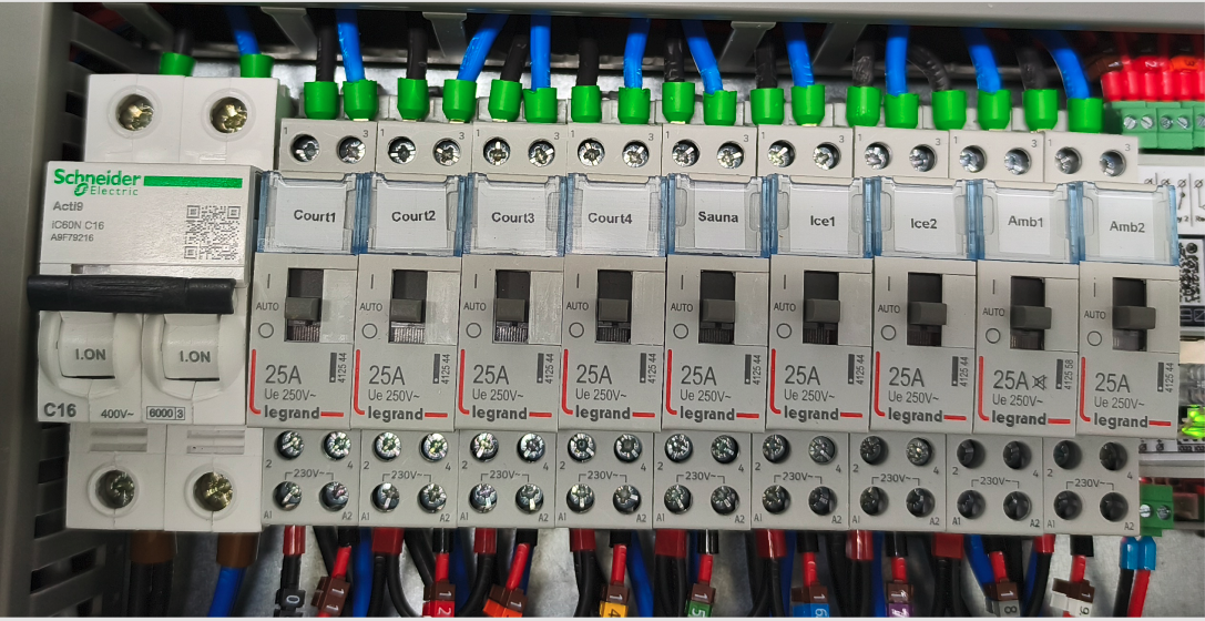
5.3 Manual emergency selectors
Include 3-position manual selectors (OFF / AUTO / ON) that allow club staff to override PLC logic and manually control lighting or other systems. They are especially useful in emergency situations, testing phases or during maintenance.
Independent Selector | Selector Integrated in Contactor |
It is wired in parallel with the PLC output. Allows choosing between full manual control, automatic logic or complete shutdown. More flexible, requires more wiring. | Some contactors (e.g. Finder series 22) include an integrated 3-position selector. Simplifies installation, reduces wiring and ensures safer transitions between modes. |
⚠️ Notes on manual selectors Selectors must be installed downstream of the relay logic and upstream of the final load. Labelling (AUTO / MANUAL / OFF) must be clearly visible on the panel. Manual overrides must be used only by authorised personnel and disabled during normal PLC operation to avoid conflicts. |
6. System Dimensions
Before planning the installation, it is necessary to calculate the number of control points in the project to determine how many PLCs are needed.
6.1 What is a control point?
- Each court lighting circuit = 1 control point
- Each NFC keypad (access) = 1 additional control point
6.2 Sizing rules
An additional PLC is required if: • The project has more than 8 control points, OR • The distance between the electrical cabinet and the access point exceeds 40 metres |
Example | Control Points | PLCs required |
|---|---|---|
4 courts + 1 main access | 5 points | 1 PLC |
6 courts + 2 accesses | 8 points | 1 PLC |
8 courts + 2 accesses | 10 points | 2 PLCs |
Electrical panel to >40m from the entrance | Indifferent | Additional PLC next to the entrance |
Do you need technical support?
If you have any questions about installation, system sizing or hardware configuration, our technical team is available to help you.
Book a Live Chat Talk directly with our technical team before installation. | Direct contact support@smartpadel.es |